


 Adjusting TR2-4A Valves
|
Macy's Garage, Ltd. America's BEST Triumph Shop! |
 Adjusting the
valves in your Triumph engine is one of those tasks which many of you try to
avoid. It’s a simple procedure that’s vital to your engine’s health and state
of tune, but it’s also easy to get wrong if you aren’t paying attention. Follow
along as I explain the hows and whys of adjusting valves, and let you in on a
couple of methods to keep everything straight while setting it.
Adjusting the
valves in your Triumph engine is one of those tasks which many of you try to
avoid. It’s a simple procedure that’s vital to your engine’s health and state
of tune, but it’s also easy to get wrong if you aren’t paying attention. Follow
along as I explain the hows and whys of adjusting valves, and let you in on a
couple of methods to keep everything straight while setting it.
‘Adjusting Valves’ is really an abbreviated term for this maintenance procedure. What you’ll actually be doing is adjusting the clearance between the rocker arm and the top of the valve. Without getting into a discussion of hydraulic lifters or overhead cams, let’s just say that all engines which utilize solid lifters (tappets) like our 4 cylinder Triumph engines, need to have this clearance checked and adjusted at regular intervals. Each engine manufacturer will have their own specification for the correct clearance, and their own specific procedure for adjusting this clearance (ex: engine hot or cold). Should you install a high performance camshaft in your engine, the correct valve adjustment may change from what was specified by the engine manufacturer, and you’ll need to follow the camshaft manufacturer’s recommended setting. If your valve clearance is greater than it should be, the valve will not open as far as needed for full power and excessive noise and wear will be the result. If the clearance is less than specified, the valve may not close completely, causing the combustion in the cylinder to ‘burn’ and ruin the valve itself.
For our 4 cylinder Triumphs, the valves are adjusted ‘cold’. Anyone who has ever adjusted valves which need to be adjusted ‘hot’ will know what a blessing this is! Clearance is .010” (ten one thousandths of an inch) for both the intake and exhaust valves on most of our Triumphs, but for all cars and various camshafts it’s not uncommon to have a different clearance specified for intakes vs exhausts. For example, early TR2’s equipped with iron rocker pedestals specified clearances of .010” for the intake valves and .012” for the exhausts. To determine which valve is which, see the description in method 2 below.
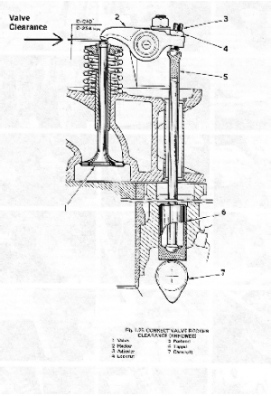
So why is it so ‘tricky’ to adjust your engine’s valves? For that answer, take a look at the valve train illustration (fig.1). The valve opening and closing (valve timing) is controlled by the camshaft (part #7). As the camshaft (A.K.A. “bump stick”) rotates on it’s axis, the egg shaped ‘lobe’ pushes the tappet up as the bump rotates under it. The tappet then forces the push rod (part #5) up, which in turn causes the rocker arm (part #2) to pivot (rock) on its shaft. Just like a couple of kids on a teeter-totter, when one side of the rocker arm goes up, the other side must go down, pushing the valve stem down and opening the valve (part #1) at the same time. To achieve the proper valve clearance, you have to be absolutely certain that the camshaft is not in a position to be exerting any upward pressure on the tappet (bump down).
But the camshaft is buried deep inside the engine, so how can you tell that it’s not at a place where the lobe is starting to ramp up toward the tappet? There are a couple of ways to do this. The first is called the “Rule of 9”, and while it works on our TR2-4A engines, it might not necessarily apply for all 4 cylinder engines. Here’s how it works:
 With the rocker cover
removed, mentally number each valve and rocker from front to rear. There are 2
valves per cylinder, so your numbers will be 1-8. I like to pull all of the
spark plugs so that the engine will be easier to rotate by hand, then I reach
down and pull on the fan blade to slowly turn the engine over (clockwise when
viewed from the front). When the #1 valve has opened fully and just starts to
close, adjust the #8 valve (1+8=9). To adjust the valve clearance, refer to
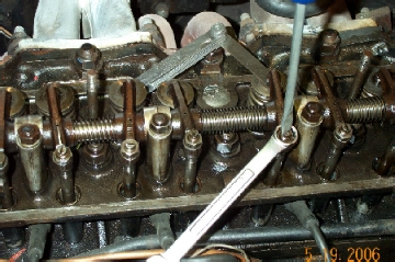
figures 1 and 2. Loosen the lock nut (part #4) with a ½” wrench, and check the
clearance with a feeler gauge of the correct thickness while using a screwdriver
to turn adjusting the adjuster screw (part #3). You will have achieved the
correct adjustment when there is a slight drag felt on the feeler gauge. Hold
the adjuster screw in position with the screwdriver while you tighten the lock
nut firmly to hold the adjustment. The adjuster screw will want to turn as you
tighten the lock nut, so you’ll probably have to apply some opposite force to
the screwdriver to prevent the screw from moving. When the nut is tight,
recheck the clearance with your feeler gauge. If it has changed from the light
drag you felt originally, loosen the nut and start over again. Continue until
the nut is tight and you’re certain that the clearance is as specified, then
move on to the next one.
With the rocker cover
removed, mentally number each valve and rocker from front to rear. There are 2
valves per cylinder, so your numbers will be 1-8. I like to pull all of the
spark plugs so that the engine will be easier to rotate by hand, then I reach
down and pull on the fan blade to slowly turn the engine over (clockwise when
viewed from the front). When the #1 valve has opened fully and just starts to
close, adjust the #8 valve (1+8=9). To adjust the valve clearance, refer to
figures 1 and 2. Loosen the lock nut (part #4) with a ½” wrench, and check the
clearance with a feeler gauge of the correct thickness while using a screwdriver
to turn adjusting the adjuster screw (part #3). You will have achieved the
correct adjustment when there is a slight drag felt on the feeler gauge. Hold
the adjuster screw in position with the screwdriver while you tighten the lock
nut firmly to hold the adjustment. The adjuster screw will want to turn as you
tighten the lock nut, so you’ll probably have to apply some opposite force to
the screwdriver to prevent the screw from moving. When the nut is tight,
recheck the clearance with your feeler gauge. If it has changed from the light
drag you felt originally, loosen the nut and start over again. Continue until
the nut is tight and you’re certain that the clearance is as specified, then
move on to the next one.
Rotate the engine with the fan blade and watch valve #2. When it is fully open, and seen to just start to close, you’ll know that it’s time to adjust valve #7 (2+7=9). Continue working your way toward the rear of the engine, watching each successive valve open fully, and adjusting the valve who’s number added to the open one adds up to 9. When you reach the rear of the engine, valve #8 is open and you’ve adjusted #1, all of your valves will have been adjusted, and the job is done.
As I mentioned before, this “Rule of 9” works on the Triumph TR2-4A engines, but it doesn’t necessarily work for every engine. For that reason, I prefer to adjust valves on a cylinder by cylinder basis, so that I know what’s going on with the camshaft of any engine I might be working on.
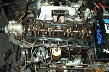 Take a look at figure
#3. Here is a Triumph TR4 engine with the rocker cover removed. We know that
there is an intake and exhaust valve for each cylinder, and you can see that
they are positioned on either side of the spark plug hole. The first two belong
to cylinder #1, the second two are for cylinder #2, and so on. Having a little
bit of knowledge of the 4-cycle engine process, I know that the intake valve is
open during the intake stroke, and the exhaust valve is open during the exhaust
stroke, and both valves should be closed during the compression and power
strokes. But which valve is which, and how do we know which stroke any
particular cylinder might be on?
Take a look at figure
#3. Here is a Triumph TR4 engine with the rocker cover removed. We know that
there is an intake and exhaust valve for each cylinder, and you can see that
they are positioned on either side of the spark plug hole. The first two belong
to cylinder #1, the second two are for cylinder #2, and so on. Having a little
bit of knowledge of the 4-cycle engine process, I know that the intake valve is
open during the intake stroke, and the exhaust valve is open during the exhaust
stroke, and both valves should be closed during the compression and power
strokes. But which valve is which, and how do we know which stroke any
particular cylinder might be on?
First, let’s decide which valve is which. This is pretty simple to do with the rocker cover removed. Look at the opposite side of the head in figure #3, and you can follow the intake manifold runners from the carburetors to the intake valve for each cylinder. You can also see that the exhaust manifold lines up with an exhaust valve for each cylinder. Now if you rotate the engine slowly with the fan blade just as it was done with the “Rule of 9” method above, you can watch each valve open and know whether the cylinder you’re watching is in the intake or exhaust stroke. By design, there is a small area between the exhaust and intake strokes where the exhaust valve is still closing and the intake valve is starting to open, so I adjust the valves of each individual cylinder as follows: When the intake valve starts to close, adjust the exhaust valve for that cylinder. There’s no way that the exhaust valve is still open toward the end of the intake stroke, and the cylinder has to go through the compression and power strokes before it starts to open again. When the exhaust valve just starts to open, adjust the intake valve, confident that the full exhaust stroke stands between the piston’s present position and the start of the intake stroke. Watching the valves in this manner, I can be certain that the camshaft bump is down for the valve I’m going to adjust. Works every time, for every engine, and I can adjust one cylinder at a time, without jumping around all over the place and having to work math problems at the same time!
With the valve adjustment complete, all that’s left to do is install the spark plugs and rocker cover. Always use a new rocker cover gasket, and even then they’re prone to leak oil so I always glue the new gasket into the rocker cover with 3M weatherstrip adhesive and let it dry before placing the cover back on the engine.